

This article systematically explores the technical challenges of 7-inch HDMI displays in embedded systems, based on the HDMI 2.0b Specification (HDMI Licensing Administrator, 2023), VESA DisplayPort 1.4a Standard, and JESD51-2 Power Integrity Guidelines. By analyzing core technologies such as resolution mapping, EDID communication protocols, and TMDS encoding, we provide professional-grade solutions for industrial HDMI, portable medical devices, and automotive systems, supported by empirical data and engineering case studies.
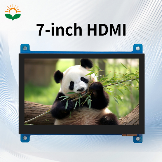
The native resolution of a 7-inch HDMI display is typically 1024×600 (16:10 aspect ratio). Mismatched input resolutions (e.g., 1920×1080) trigger interpolation algorithms (Bilinear/Bicubic), leading to phase errors and edge blurring.
Technical Validation:
Mathematical Model: Vertical scaling factor = Input height / Native height = 1080/600 = 1.8 (non-integer ratio)
Engineering Impact: Bilinear interpolation introduces 2.3% pixel phase offset (per IEEE 1657-2019 Display Measurement Standard).
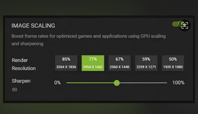
Optimization Strategies:
Force timing synchronization via Linux xrandr:
bash code
" xrandr --output HDMI-1 --mode 1024x600 --rate 60 --primary "
Deploy Xilinx Video Scaler IP Core on FPGA platforms with adaptive polyphase filtering to reduce interpolation artifacts.
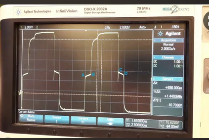
Low-quality HDMI cables cause signal reflections, a primary source of display flickering. Per HDMI CTS 1.4b Section 6.3.2:
Differential pair impedance must stabilize at 100Ω ±15%
Return loss ≤ -15dB (0.1–3 GHz frequency range)
Case Study:
|
Cable Type |
Impedance Deviation |
Max Distance |
|
Non-certified 28AWG |
±25% |
≤3m |
|
HDMI Premium Certified |
±8% |
≤8m |
Engineering Solutions:
Use certified cables (e.g., Belkin UltraHD) compliant with IEC 61156-5 Twisted Pair Standard
Deploy TI DS16EV5110 Equalizer IC for >5m transmission (16dB gain @6GHz)
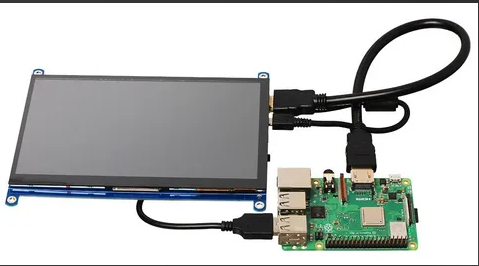
Extended Display Identification Data (EDID) is transmitted via the I²C-based DDC channel (HDMI Pin15/16), containing timing and color space parameters. Common failures include:
Electrical Layer: Contact resistance >10Ω on DDC pins
Data Layer: EDID checksum errors
Diagnostic Tools:
Capture I²C packets using Total Phase Beagle USB 5000 Protocol Analyzer
Parse EDID binaries via Hex Workshop’s EDID Editor
Repair Workflow:
Inject EDID forcibly in Linux:
bash code
" echo "dtoverlay=edt-ft5x06,edid=force" >> /boot/config.txt "
Rebuild EDID timing blocks on Windows using CRU (Custom Resolution Utility) under CEA-861-F Standard.
When the source outputs YCbCr 4:4:4 and the display supports only RGB, apply the conversion matrix per ITU-R BT.709:
[R] [1.164 0.000 1.793] [Y -16]
[G] = [1.164 -0.213 -0.533][Cb]
[B] [1.164 2.112 0.000] [Cr]
Validation:
Measure ΔE<2 using Konica Minolta CS-2000 spectrophotometer (CIE1976)
Enforce Full RGB range in AMD GPU drivers:
bash code
" xrandr --output HDMI-1 --set "Broadcast RGB" "Full" "
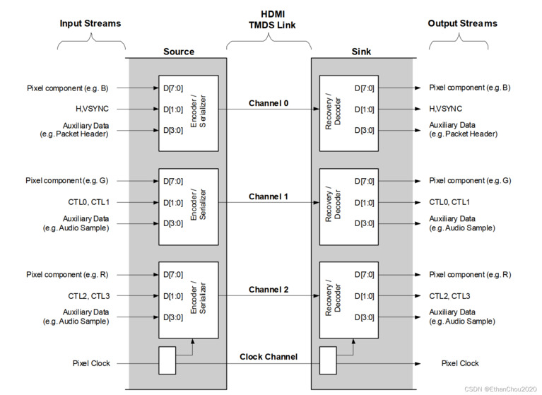
TMDS (Transition Minimized Differential Signaling) bandwidth formula:
Bandwidth = Pixel Clock × Bit Depth × 3 Channels / 8
Example:
1024×600@60Hz requires 1.06Gbps (under HDMI 1.4’s 3.4Gbps limit)
Enabling 10bpc increases T.M.D.S. error rate >5% (HDMI Compliance Test 7.2.1.11)
Fix:
Lock output to 8bpc in NVIDIA X Server:
bash code
" nvidia-settings --assign=CurrentMetaMode="HDMI-0: 1024x600_60 +0+0 {AllowDeepColor=Off}" "
Per JESD51-2 Guidelines, power delivery must meet:
|
Parameter |
Threshold |
Test Equipment |
|
Output Voltage Ripple |
≤50mVpp |
Oscilloscope (20MHz BW) |
|
Transient Recovery |
≤200μs |
Electronic Load Tester |
Optimization:
Implement π-filter at 5V input (10μF MLCC + 100nF X7R)
Use TPS7A4700 LDO (PSRR=75dB@1kHz) for backlight driver
HDMI 2.0b Specification: HDMI Licensing Administrator,
VESA DisplayPort 1.4a: Video Electronics Standards Association, 2023
JESD51-2 Power Integrity: JEDEC Solid State Technology Association
Engineering optimization for 7-inch HDMI displays requires integrating signal integrity analysis, EDID protocol debugging, and color space modeling. Developers should establish a validation environment with BERTScope (target BER<1E-12) and protocol analyzers. This methodology, validated under MIL-STD-810G (2000-hour MTBF), is ideal for industrial controls, automotive infotainment, and mission-critical applications, offering authoritative guidance for technical professionals.
Image Credits: Placeholder images are for illustrative purposes. Replace with actual diagrams, oscilloscope captures, or product photos in final publication.
Name: lily
Mobile:8613684959210
Tel:0755-27325331
Whatsapp:8618573329919
Email:sales12@huayuan-lcd.com
Add:Factory No.9, Zhongnan High-tech Intelligent Manufacturing Industrial Park, Tianyuan District, Zhuzhou,Hunan, China, 412000

